Because we are outsiders who recently moved into a small mountain community (we are 'city people' in the eyes of the locals) one of our long term goals here on the mountain is to ingratiate ourselves into the community by demonstrating that we are good neighbors with value to offer that can be counted on when needed. This little project helped to kick start that process.
Shortly after we moved here we discovered that we needed the services of a professional contractor. Immediately we began looking locally since whenever possible we prefer to buy (and sell) locally to keep the money in the community. We quickly found that the person we needed (with a small crew of workers) was just down the road a few miles from us.
The first time he and his crew came by to begin work I struck up a conversation with the owner. While we come from very different worlds we seemed to hit it off. He was curious about this outsider and found me interesting. I talk and dressed differently, but I seemed harmless enough. And he was very bright and articulate and knew his business inside and out.
The second time he was back I told him I planed to install a standby generator myself, doing everything except the propane installation. He told me he was thinking along the same lines and we compared notes. The third time he came back I was already knee deep into the generator installation and he saw that I had not killed myself.....yet. At that point he told me he had decided to go with a large portable generator, 17.5kws to be exact.
About a month later his wife, who runs his business office, emailed me to ask if I could come over and meet with her husband to discuss helping him hook his new generator into his home wiring system. I jumped at the chance to help out my new friend and was over there the next day.
The Situation
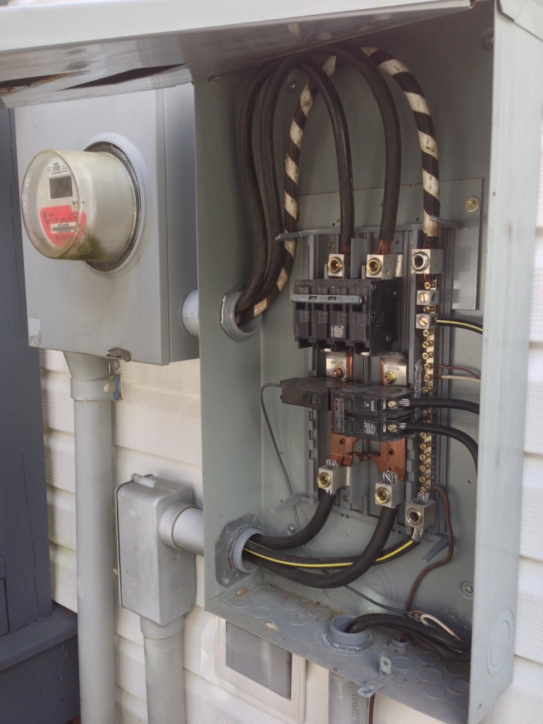
Up to this point my friend had used a smaller 5000 watt portable generator and back fed it into his home's electrical system by shutting down the main 200 amp circuit breaker at the meter outside, then plugging the generator into the 30 amp welding outlet in his garage and back feeding the generator's power into the house. He understood that he needed to isolate the home from the utility line when using the generator or he ran the risk of injuring a utility lineman or a neighbor.
His main feed was a little funky, as I have found many homes around here are. His house was built first, then a few years later he built his very large garage/business workshop and ran power out there from the house. The good news was that the utility power came in underground and up into his meter. It then was routed into a main 200 amp exterior rated panel. From there he had installed a separate 100 amp circuit breaker below the disconnect which fed the garage circuit breaker panel. The house electrical panel was fed directly off the 200 amp main circuit breaker. There is also a small 20 amp circuit breaker feeding an outside outlet below the panel.
His original plan was simply to feed his new (essentially 75 amp) 17.5kw generator into the sub panel in the garage (using a much heavier panel input than the current 30 amp welding plug) and feed the house the same way he had done with his much smaller generator. I looked over all his sub-panels, his main disconnect and the house main panel while taking many photos along the way. I asked lots of questions to understand what it is he wanted to do rather than how he wanted to do it. I wound up returning several times to re-examine the system and talk to him some more.
Then I did my research both on his current wiring setup and his portable generator. Initially I didn't look too closely at the generator other than to examine the output plugs and surge capacity. I almost made an error here, but caught myself when something about the generator didn't compute.
My friends assumption, which initially became mine by default, was that we could just hook the new generator up as he had done before with just a heavier cable. We would not need to upgrade the wiring from the garage to the house because it was already wired for 100 amps and the generator maxed out at 75 amps, 85 if you counted the surge capacity.
But something wasn't right and I couldn't figure out what, so I went to the Generac web site and downloaded the portable generator technical manuals and started haunting various web blogs frequented by electricians who work with generators. What I found surprised me and a few other electricians judging by the responses on the blogs.
What had me searching for something that I felt was wrong was the fact that while the 17.5kw Generac portable generator could put out 240 volts at 75 amps (plus or minus) the largest output plug was rated at, and protected by, a 240 volt 50 amp circuit breaker. There was also a 240 volt 30 amp output and the assumption by the owner had been to use two plugs wired into the same garage sub-panel to gain the total output of the generator. But why would Generac put only a 50 amp outlet on a machine that could put out 75 amps?
It turns out that the answer is the national electrical code which restricts all portable generators to a maximum of one 50 amp 240 volt outlet. There can also be other outlets, such as a 30 amp and a 20 amp. But here is the kicker. All the outlets are not phase synchronized, which means that if they are plugged into the same circuit panel any electrical motors running off that 'dirty' power will burn up and other issues will rear their ugly head. You simply cannot combine power sources that are out of phase.
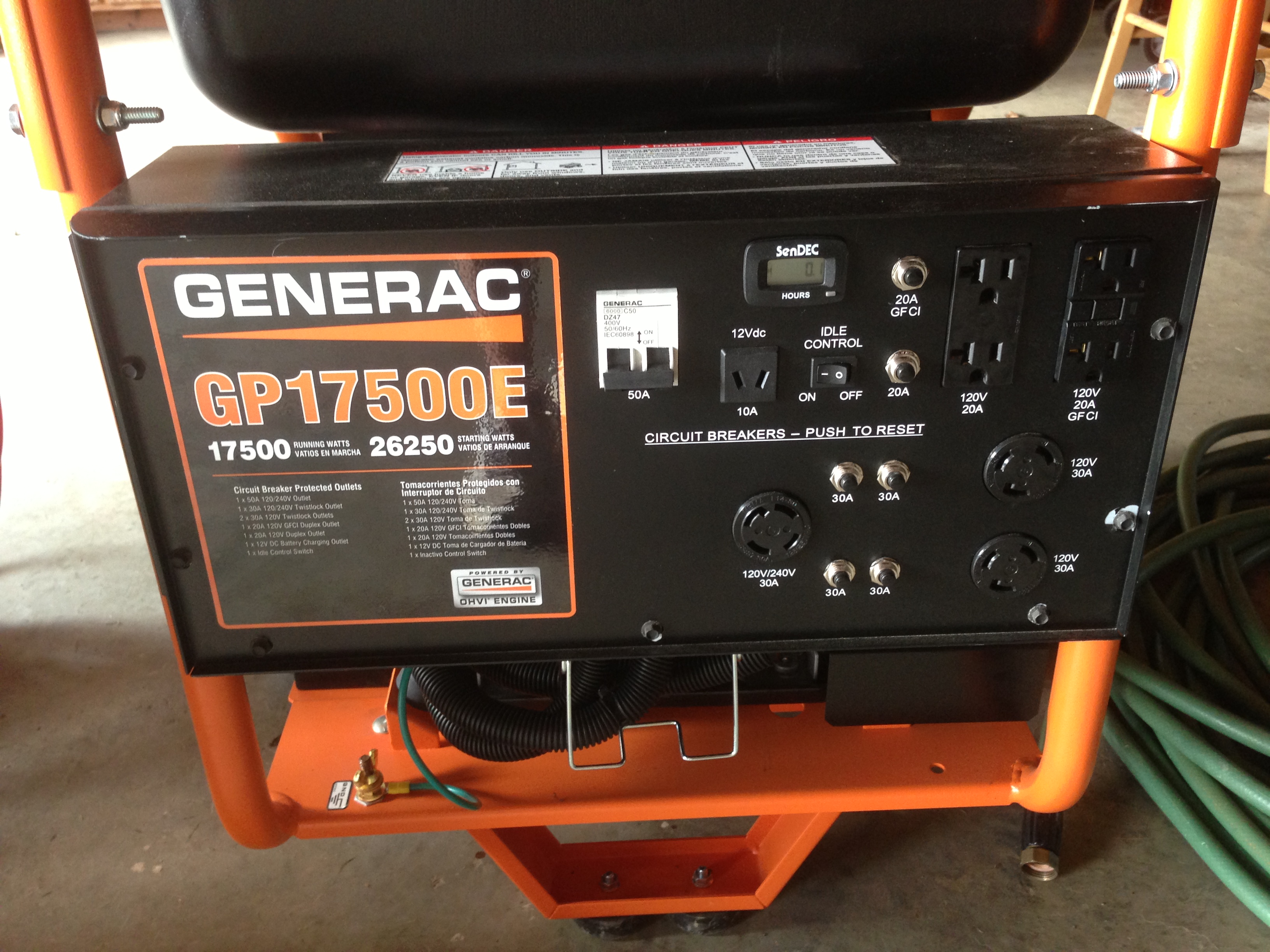
The 50 amp 240 volt output cable is plugged into the bottom of the control panel. The Generac portable GenSet pictured above is essentially the same engine and generator as my permanently installed Generac 17kw standby GenSet except this one is powered by gasoline, giving it a surge capacity and more flexibility. But it is even less fuel efficient than mine while using more expensive, and potentially harder to find, fuel.
So what do I do? Initially I went back to my friend and explained the situation. While he didn't understand what 'phase' was he was resigned to only having 50 amps available to power his house and garage. It was still 2.5 times greater than his old generator was capable of producing. But something told me I could wire this sucker to utilize all it's output if only I thought about it long enough.
Long story short what I needed to do was to treat his house and garage as entirely separate circuits. This way I could use the 50 amp output to feed the house and the 30 amp output to feed the garage/business workshop. This way is did not matter if the two generator outputs were out of phase since the two panels would be separated and the power never mixed.
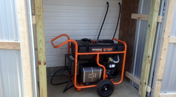
My friend's other requirement was that he wanted to build a shed with doors behind the garage where he would store the portable generator. When it was needed he could simply prop open the doors and fire it up, then do whatever he needed to do with switches to disconnect the utility and engage the generator. I suggested he use a flexible pipe to vent away the exhaust gases from the generator so they aren't sucked into the intake and stall the engine. He took my suggestion under advisement.
The only other issue he vetoed was installing a whole house transfer switch at the meter to mechanically disconnect the utility before engaging the generator circuits. He felt his method of flipping the 200 amp main off nest to the meter was sufficient. While I disagreed it was his show and his generator. Instead I tried to compensate for this omission by building other safety steps into the system.
First off I needed to install a simple 100 amp transfer switch in the electrical feed line between the house and the garage sub-panel. This was needed so that I could isolate the garage from the house when on generator power. But I also needed to send the 50 amps of generator power back to the house using the same feed cable. I decided to place that transfer switch physically under the garage sub panel where it was easiest to intercept the feed cable before it entered the garage sub panel.
I'll skip all the details and just say that it was a bitch taping into the feed conduit coming up into the sub panel so that I may insert the transfer switch without cutting the wires inside. Obviously I cut the power in that line while I was working on it. But it is nearly impossible to cut a plastic conduit without cutting what is inside. So I didn't cut the conduit. There was a coupler near the floor and I chiseled it off, allowing me to remove a section of the conduit between the coupler and the sub panel. The feed cable was aluminum and not easy to maneuver in the colder weather.
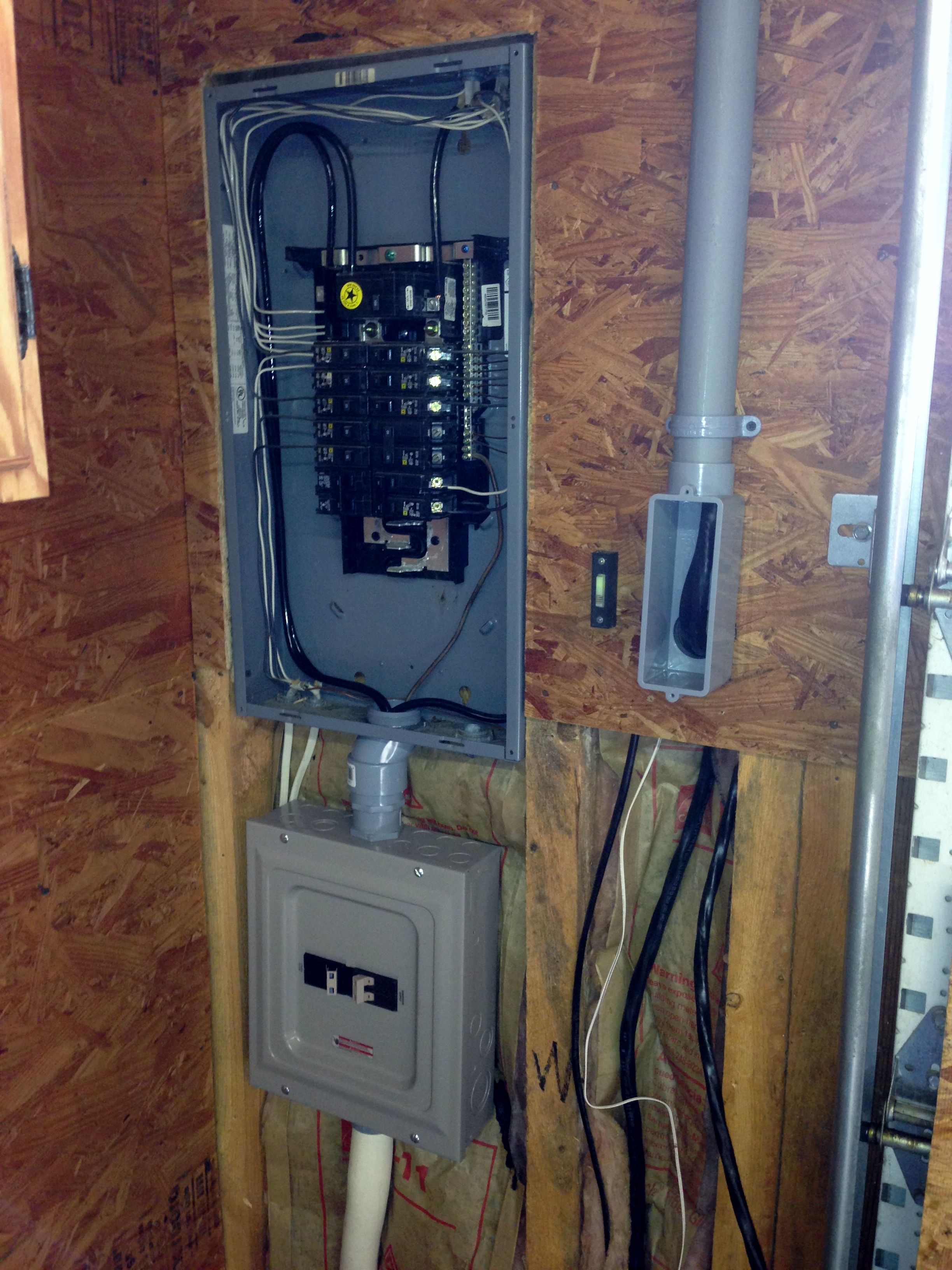
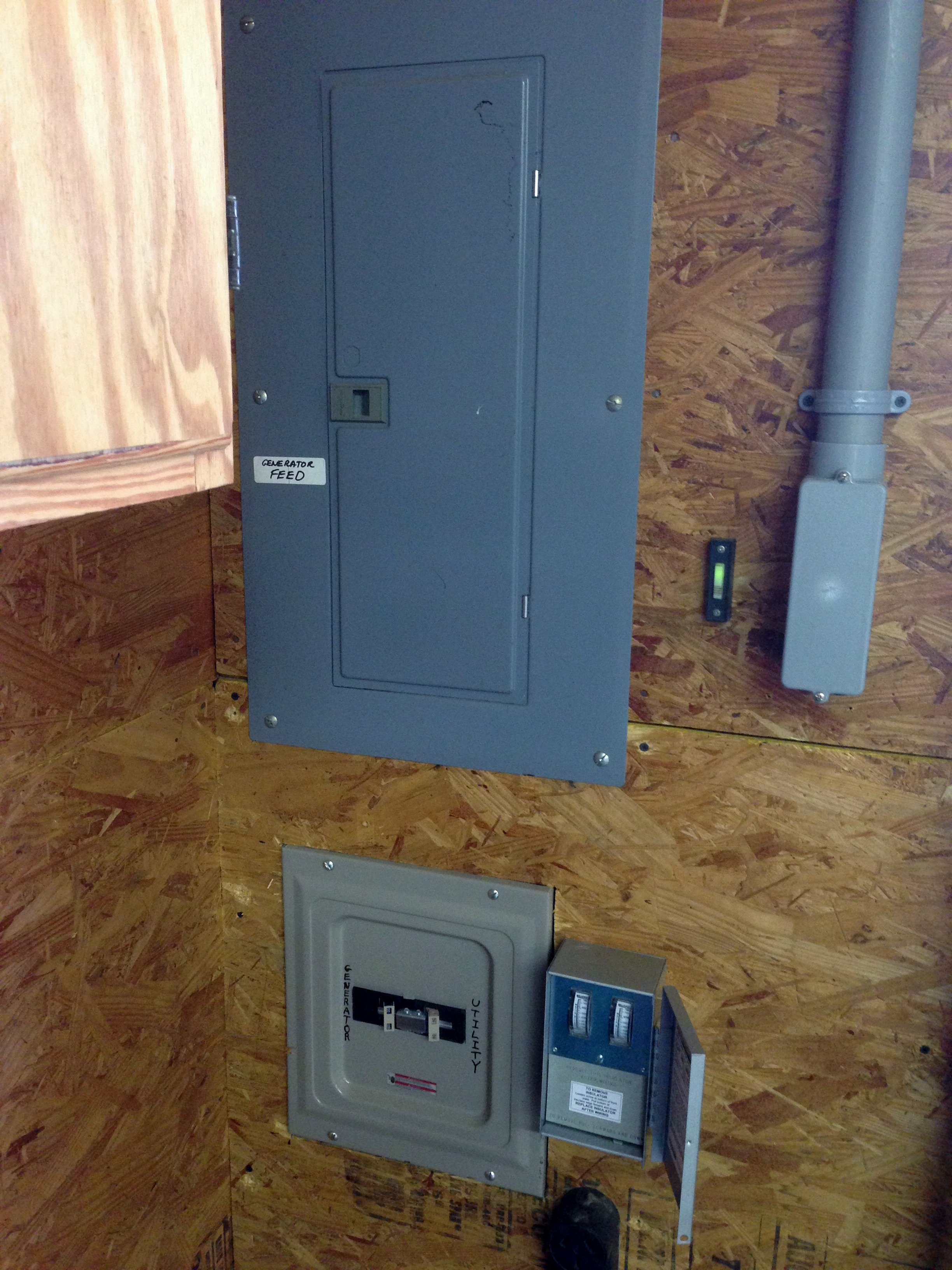
Below you can see the garage sub panel which is located on the front wall of the garage next to the garage door. Below it is the semi installed transfer panel with most of the wiring done except for the feed coming from the back garage wall. Coming down from the top right is the conduit from the back wall that ran along the ceiling that contains two sets of generator feed cabling, one 6 gauge and one 4 gauge. I sized the conduit to handle more than twice the cabling used, so no worries about heat buildup.
I decided to place two cutoff switches on the back wall of the garage where the two low temperature flexible cables entered from the shed behind the garage. I wanted to give my friend a positive shutoff to disconnect both the 30 amp feed for the garage and the 50 amp feed for the house from inside the garage. I always wanted at least two places where the generator feed could be shut off in addition to the generator itself.
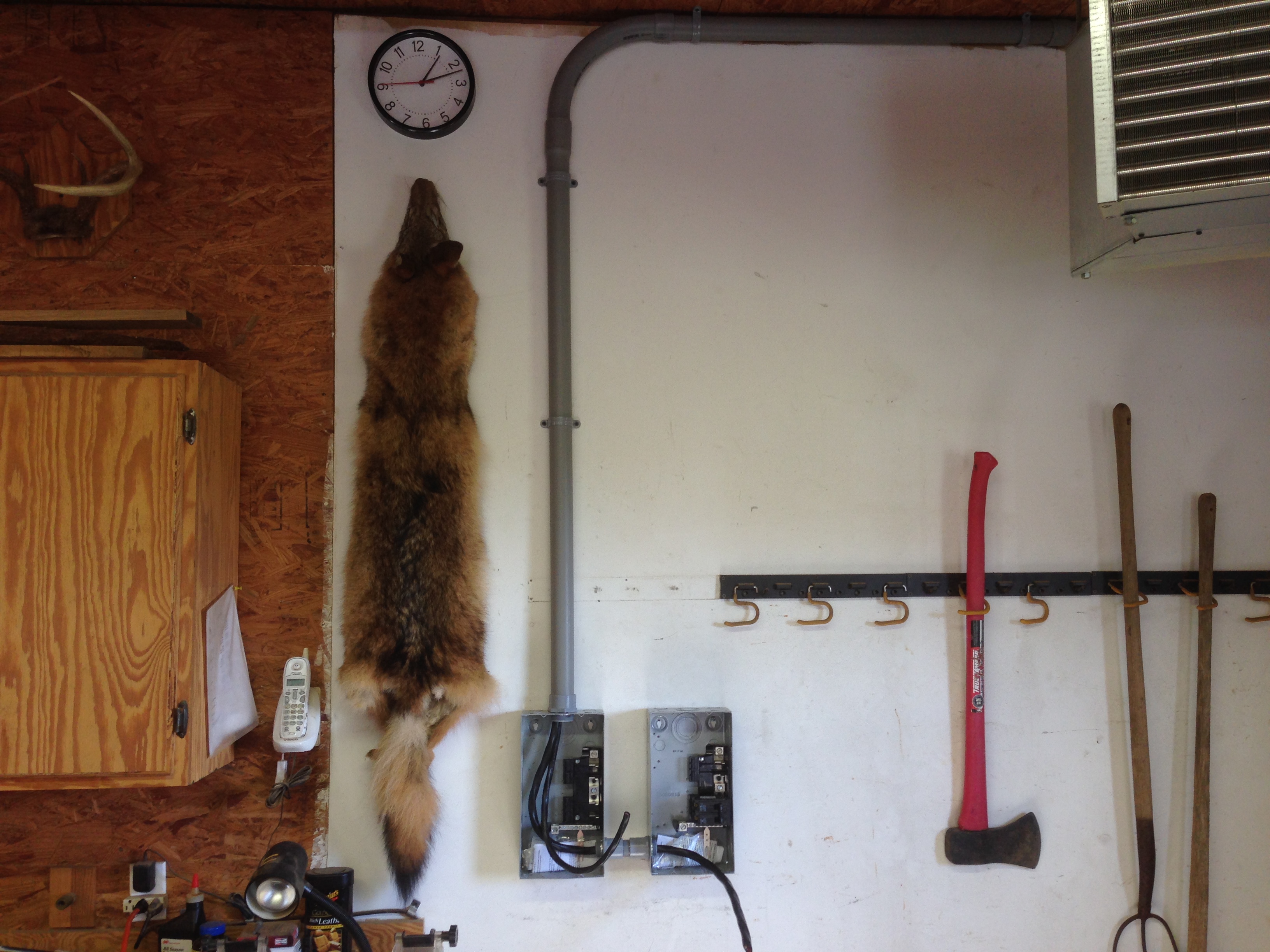
In the picture below you can see the two wall mounted small circuit breaker panels, one 50 amp and one 30 amp, as well as the conduit that runs to the front of the garage where the sub-panel and transfer switch are located. The two flexible feed cables from the generator feed directly into each panel from the backside. The picture at the very top of this article shows the generator inside its shed. It also shows those two flexible cables connected to the generator and running through the outside wall. Those cables run into these two boxes.
And Yes, that is a fox hanging on the wall.
BTW, my friend heats both his home and his workshop/garage with a wood stove boiler and you can see the garage heat exchanger/fan hanging from the ceiling in the upper right of this image.
Below is an image of the completed garage sub-panel modification with the transfer panel below it, the generator feed conduit on the right and a meter placed to the right of the transfer panel to monitor the 50 amp feed going to the house.
I wasn't too concerned with my friend exceeding the 30 amps feeding the garage. He understands that when the generator is on one must always think about total power consumed before turning on any heavy motors. But the house is a different matter and doing normal household stuff while on the generator can easily exceed 50 amps. As well we knew that all 240 volt appliances in the house would be mostly balanced between the two 120 volt sides, but that the rest of the house, meaning lights, outlets, refrigerator and freezer etc that run on 120 volts might unbalance the system if they were clustered to one side or the other of the main house panel.
I installed the meter so that when his generator is running he can come out to the garage and see if both sides of the electrical load going to the house are pretty even with just a glance. If it is consistently unbalanced I can come back and move some of the unbalanced load from one side of the main house panel to the other side. Too heavy an unbalanced load run for too long can damage the generator.
One of the things I was worried about when building this type of hybrid system is for someone who doesn't know what they are doing, or worse thinks they do, to come in and start throwing switches. I told my friend that I wanted to build in some redundancy in order to increase safety and then create simple instructions that allow someone who has never seen the system before to know how to start things up, shut down to refuel and then start up again, and finally shut it all down when utility power comes back on.
If you notice in the image above I have clearly labeled the transfer switch, though what you don't see is that I labeled it to make intuitive sense, which is just the opposite of 'code". The national electrical code only makes sense to an electrician, and then only half the time.
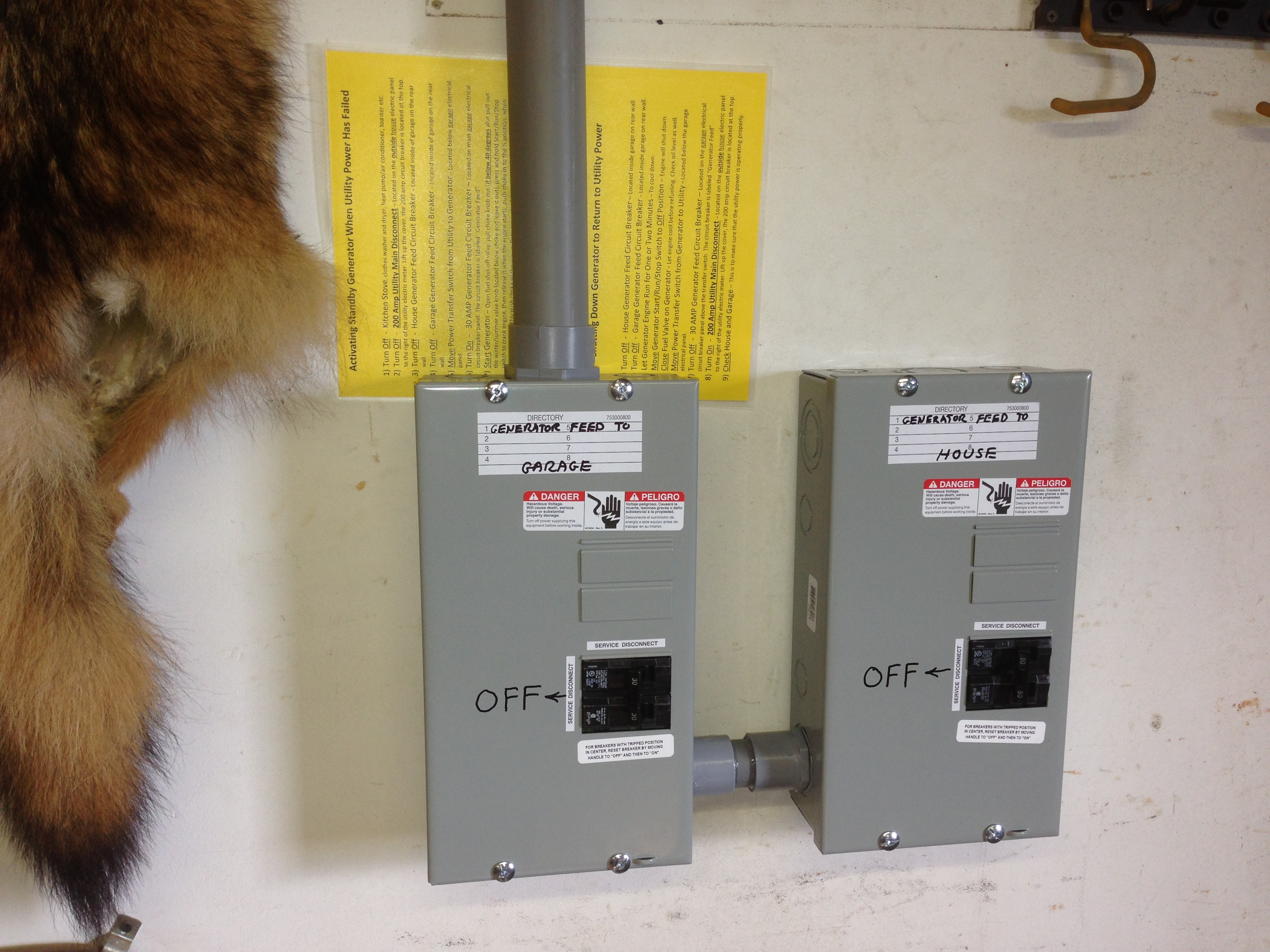
Below is the finished cutoff switches for both the 30 amp garage feed and the 50 amp house feed. Again they are clearly labeled, only in this case I wanted it to be crystal clear which way was OFF. In an emergency you want to know how to turn things off and once again the code labeling is confusing. The new panel labeling is not.
Slipped behind the conduit are the printed instructions I created for the system. They were printed on yellow paper and then laminated. The only thing worse than confusing instructions are instructions you can't find and yellow paper is easy to find even when mixed in with white paper.
I printed out 6 sets and placed them on the generator, behind the back wall conduit, hanging from the transfer switch itself, inside the exterior 200 amp panel near the power meter where you disconnect from the outside world and two in the hands of my friend's wife so that she may start the system if hubby ain't home and the power goes out.
Ultimately the 30 amp garage generator feed can be shut down from the generator, from the back wall panel and from a 30 amp circuit breaker I installed in the garage sub-panel. If you scroll back up to the picture of the finished garage sub-panel and transfer switch you can see a label on the outside of the sub-panel that says "Generator Feed". Inside the door you will find that 30 amp circuit breaker.
The 50 amp house generator feed can be shut off at the generator, on the back wall of the garage, at the transfer panel and at the 100 amp circuit breaker found inside the panel next to the house electrical meter. The instructions always begin by shutting down the outside world with the 200 amp disconnect next to the meter before any other switches are thrown to start up the generator and feed the system.
The reverse is the case when the utility power comes back up. Everything else is shut down and switched over before the operator is told to turn the outside world back on. Those steps are in big bold black oversize type. The instructions show a step by step process of what exactly to do first, second, third and so on.
After we had tested the system and all was OK I reset the generator system to off and grabbed one of his employees. I handed him the instructions and told him the power had failed and to start up the generator system. Then I shut my mouth and watched him go through each step while I looked for flaws in my instructions. Even better, the employee was nervous working around electrical power so I'd picked the perfect test case. Both generator start up, refueling and shut down worked flawlessly and no instruction changes were needed. My friend was most pleased.
Before we had started this project my friend and I had agreed to barter our services so no cash changed hands. I quoted him a very fair price for my labor with him buying the parts. And even though I ran over on the hours I stuck to the price. I was building goodwill here and my loss was more than compensated for by the community connection I was making. It was a win win situation all around.
Cognitive Dissonance
To cut PVC conduit without damaging the conductors inside use a length of mason line. Wrap the mason line around the pipe and pull the line in a reciprocating movement. The mason line will cut right through the PVC. You may have to change the line if it wears smooth and replace it with a fresh piece. This method works great when cutting PVC pipe in a trench.
Watch your fingers, the line gets hot. Wish I had been there to help you. I love challenging projects. Contact me about you deer fencing, I have a LOT to say.
Thanks for the tip. I shall contact you regarding the deer fence.
Cognitive Dissonance
Oh my god Cog, I understand you American’s like things big over there, but what sort of loads are you running to ever require 17kW?? Do you know how much energy is wasted by running this kind of genset without drawing anywhere near that kind of load.
Let me give you of an idea of my set up. I designed it as back up for my solar storage system. First I analysed my biggest loads:
-Bore pump 650 w
-Heat pump hot water system 500 w (COP of 4)
-Heat pump AC/Heater 800 w (COP of 7!!)
Therefore I bought a 1000 watt inverter generator and modified it to run on LPG and gasoline. With smart load management, it can cover all my highest loads, so long as I run them separately. The spare 200 w, assuming I just had to have the AC on, (e.g. we can get 3 days in a row of over 110 F) will keep the fridge cold and the lights on. Passive solar heating and cooling design of the house, means the reverse cycle AC rarely needs to be used. For extended periods of a disabled system, a 3 way fridge (that runs on LPG – which has an almost infinite shelf life) will be used. I get immense joy in minimising waste, and designing systems for an optimum performance. I would be very depressed with a 17000 w genset.
Kooka,
Just our well pump alone requires 35 amps @ 240 v to start from locked rotor and 6 amps @ 240V to run. The same for any large electric motor over here. The loads are simply much higher than you are quoting.
Cognitive Dissonance