By
Cognitive Dissonance
The following is the third of three articles (this one by far is the longest) outlining the research, preparation and installation of the Simple Pump, a high quality mechanical pump used both in everyday applications such as a ranch, farm, off grid cabin or homestead as well as an efficient backup to an existing fresh water pumping system. These are long reads, not brief outlines, and apply only to our specific situation and location. Your experience can and will vary from ours.
I am using specific technical terms for parts and processes in this section which I do not always fully explain. Please revisit Part One and Two for a clearer understanding of the definitions and methods employed. Also, this was written with the novice in mind, which means I go to great lengths to explain many things a more experienced homeowner or professional already knows and takes for granted. Please be patient.
In Part Two of this series I installed the Simple Pump modified Pitless adapter and the entire drop/discharge pipe and sucker rod bundle (15 sections in all) into the well casing. At that time I did not install the check valve assembly connecting the Simple Pump discharge to the line headed towards the house, preferring to check the Simple Pump for proper operation before doing so.
It was only when I began the final assembly of the pump head and lever arm that I discovered a missing component, the modified Pitless adapter ‘rod gland’. The rod gland is essentially a rod guide and seal assembly that screws into the top of the modified Pitless adapter which enables a stainless steel rod to transmit the mechanical movement from the pump handle to the sucker rod below while also sealing the water inside the Pitless adapter. Normally there is no topside penetration of a ‘standard’ Pitless adapter, thus the critical need for the ‘rod gland’ to seal that penetration.
My email to Simple Pump was once again quickly answered by the president of the company, Gary Wittig, who had good news/bad news for me. He would indeed send me the missing part once it had been restocked in a week to ten days. He did as promised and the package was delivered just over a week after my email. Thank you very much Gary. Clearly you understand the value of quality customer service.
With everything now finally in hand I began the final Simple Pump head and lever assembly. Because I was routing the pumped water through the side of the well casing via the modified Pitless Adapter, the final assembly varied a bit from a ‘standard’ head and lever installation.
Normally the drop/discharge pipe connects directly to the pump head and the water is routed up through the pump head and out a hole near the top. The sucker rod inside the drop pipe (which drives the actual ‘pump’ at the bottom of the drop pipe) is connected to a stainless steel rod which passes through the pump head and out the top where it attaches to the lever arm.
When you move the lever handle up and down you are moving the sucker rod inside the drop pipe which in turn drives the pump at the bottom. The pump then pushes water up inside the drop pipe and out the pump head. It really is an amazingly simple, self contained and efficient hand pump system, particularly because it is so well engineered and manufactured.
When using the modified Pitless adapter, the water exits out the side of the casing below ground via the modified Pitless adapter rather than up through the head. However, the sucker rod/stainless steel rod must still continue on up through the Pitless adapter, then through the head to connect to the lever arm just like it does with a ‘standard’ installation. Therefore the top of the Pitless adapter must be modified to allow the sucker rod/stainless steel rod to pass through while still containing and directing the water through the side of the Pitless.
This feat is accomplished by using the formerly missing ‘rod gland’, which screws into the top of the modified Pitless adapter and contains a rubber seal inside to allow the stainless rod (which is connected to the sucker rod below) to move up and down while containing the water inside the Pitless.
In practice, the drop/discharge tube accepts an eighteen inch drop tube adapter section which screws into the bottom of the modified Pitless adapter. The sucker rod inside the drop pipe is attached to a smooth, approximately two feet long, stainless steel rod. This rod then passes through the top of the modified Pitless adapter and the rod gland.
The transition from sucker rod to smooth stainless steel rod is needed in order to mate well with the seal inside the gland rod. That rod is made of stainless steel so it won’t rust. The fiberglass sucker rod would not seal well inside the rod gland, therefore it is no longer used at this point. The water is now contained inside the Pitless adapter and directed out the side of the well casing, while the up and down movement from the head and lever arm assembly is effectively passed down through the Pitless adapter to the sucker rod and then to the ‘pump’ at the very bottom.
Once the smooth stainless steel rod (which is connected to the sucker rod below) passes through the rod gland sealing the water in the Pitless adapter, it terminates and is attached to an ‘all thread rod’, basically a plain steel rod completely covered in threads. Think of a six foot long screw without a head or point. This is cut to length (see the instructions to determine the proper length) so it exits the top of the well casing cap.
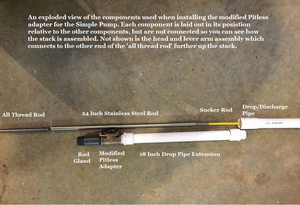
Please excuse the poor image above. As I was grabbing the components from the basement I realized I had not taken an exploded view photo. I arranged them in order on the basement floor, shots some pictures and then returned to the well to install them.
The notations on the image match the description in the text and will help you decipher the article.
From there a second slightly different two foot long smooth stainless steel rod is attached and inserted inside the pump head and out the top where it is attached to the lever arm. Presto, one working Simple Pump with the water rerouted through the side of the well casing rather than up and out the head.
I urge you to peruse the installation manuals and videos on the Simple Pump website, which are worth several thousand of my words. While my dream is to become a technical writer for Sears and Roebuck, Lawn Mower division, :-) it is difficult to explain a mechanical process without the aid of images.
Using the Pitless adapter simplifies the head and lever installation because you no longer must worry about holding the weight of the entire drop pipe/sucker rod/pump stack while feeding it through the well casing cap. The Pitless adapter is carrying all that weight. However, with the standard installation, all that weight helps to stabilize the well casing cap while you apply torque to the cap from the pumping action. You don’t have that helping hand when using the Pitless adapter and that was a unique problem (one most people will not experience) I will address later on.
Once the head and lever were installed I tested the Simple Pump for proper flow out of the one inch plastic pipe I had attached to the modified Pitless adapter, but had not yet integrated into the main submersible pump line running to the house. Because the drop/discharge pipe was already mostly filled with water (see Part Two for that epic feat of stupidity) it only took a dozen movements of the lever arm to get water flowing out of the discharge pipe. I then turned my attention to the check value assembly.
To briefly recap, I wanted to be able to pump water directly into my home’s fresh water pressure tank in the basement, described by Simple Pump as ‘pumping into pressure’. I could have done so indirectly via a ‘standard’ Simple Pump installation where the water comes out the top of the pump head and is then directed into the basement pressure tank via a (long) potable water hose attached to an outside (non anti-siphon) faucet.
But during freezing weather, each time I was done pumping water I would need to remove and drain the hose, then bring it inside or leave it in place and run the risk of the hose freezing and splitting. As well, the constant connecting/disconnecting and draining of the hose greatly increases the risk of introducing contaminates into my fresh water system, particularly if I was dealing with a long term loss of main submersible pump/electrical failure.
When planning this installation I was thinking worst case scenario and wanted to mitigate the potential for failure wherever I could. The only thing worse than having no fresh water is thinking you do and making yourself (and everyone else in your house) sick from bad water.
Now you are desperate for fresh water because you are sick and have no recourse unless you sanitize the entire system and start again, a very difficult process with the low flow rate from the Simple Pump. Or you go (back) to hauling buckets of water inside, which sort of defeats the reason you are “pumping into pressure” in the first place. In my book, the order of the day is ‘better to be safe than sorry’.
The method used to integrate the Simple Pump into the household fresh water system is to merge into the main water line coming from the submersible pump and feeds the pressure tank in the house. Always remember, it is the submersible pump at the bottom of the well that actually pressurizes your household fresh water system. The reason the water rushes out of the faucet is because the submersible pump has pumped that pressure into the water holding tank. The Simple Pump will do the same thing, albeit much slower and powered by hand rather than electricity.
Water takes the path of least resistance. Therefore two one-way ‘check’ values must be installed in the ‘merge’, one coming from the submersible pump and one coming from the Simple Pump. When the submersible is operating, you do not want that pump to feed water back down the Simple Pump via the ‘merge’, aka the path of least resistance.
As well, when the Simple Pump is pumped by hand, you don’t want that water feeding back down the pipe to the submersible pump. One way check values (water is allowed to flow in one direction, but not the other) prevent this from happening. When installed properly on each feed ‘line’, they prevent each pump from back feeding the other.
May I interject with a huge cautionary note at this point? You should plan to spend at least an additional $125 for the components that make up your check valve assembly. They are not included with the Simple Pump. Do not go cheap here. You are burying this assembly underground where it might remain for many years, decades even.
You want the system to work during an emergency and to continue to work for as long as needed. A failure of any component at that time could be disastrous and even life threatening. Going with cheaper components might save you $25 - $50. Is it really worth it?
Go with the highest quality you can afford and purchase brass check values and fittings. Use threaded pipe ‘goop’ and nylon tape when making all your threaded connections. And for goodness sake, use only high quality stainless steel adjustable pipe clamps and make sure you double them up at every connection to the plastic water pipe.
Most modern residential water lines are one inch (inside diameter) ADS plastic pipe rated for 100 PSI and certified to meet NSF 14/61 standards for potable water usage. But you might discover a ¾” or 1¼” pipe feeding your house. Match the size of your check valves and fittings to the situation at hand.
After digging it all up, if you find an obviously outdated and inadequate pipe or connection, I urge you to upgrade it before adding the Simple Pump to the system. Fix or upgrade everything while you have the system exposed or you will do so later at the worst possible time. An ounce of prevention is worth a ton of cure.
Did I mention to cut the power to your submersible pump, and then double check power is off at the electrical connection in the well casing (if possible) before you break into the existing water line. Failure to do so will create a gusher and rapidly fill your hole with water as you desperately run to the house to shut off the pump.
After you kill the power and before you cut the line, make sure you locate the shut off value used to isolate the pressure tank from the rest of the house’s fresh water plumbing. There might even be a second valve between the pressure tank and the well. If so, shut that one off as well. Failure to do this will result in you draining most of the water from the holding tank, if not the entire house, once you break into the water line at the well, potentially filling the hole at the well casing with water.
Once the shut off valves are closed you can cut into the water line and the only water that should spill out is the water in the pipe itself. That will drain out quickly. Use a proper plastic pipe cutter to make clean cuts. If you don’t have a plastic pipe cutter, purchase one. It is so much easier and professional to make the new connections when the ends of the plastic pipe are cut off clean and even.
Caution! If you are like most people, you dug your hole only wide enough to uncover the pipe a foot or so from the casing. This won’t be nearly enough, so before you cut into the pipe, grab the shovel and uncover some more pipe; at least another foot and I suggest two.
The reason is simple. You are going to cut out and remove a section of the plastic pipe about an inch or two less than the width of the check valve assembly being inserted into the opening. That is nearly a foot, leaving you no room to work if you only have a foot of pipe uncovered.
You want the cut section to be a little shorter than the width of the check valve assembly so the plastic pipe tends to remain seated on the ribbed connectors if the pipe clamps degrade or loosen. In other words, you do not want tension pulling the plastic pipe away from the connectors. Instead you want compression forces pushing them even tighter together.
If it is too tight you can always cut a little more of the pipe off. But if it is too short, you can’t add more plastic pipe without making another ‘splice’. The more connections you make, the more potential points of failure you have. Measure twice and cut once. Be conservative. You want the hole you dug wider than you think you need because you must bend one end of the plastic pipe quite a bit in order to slip it over the ends of the connectors. You can’t bend it if you only have a few inches of wiggle room.
It’s going to be muddy in the hole because the water from the pipe has drained into the hole. Do you really want to be messing around in a muddy hole because you found out after the fact the hole you dug wasn’t wide enough?
Yeah, I thought so. Dig it wider than you think you will need because you will need it.
Warning One! I have included a picture of the check valve assembly before it was installed and after for a reason. When measuring the assembly to determine how much water pipe you must cut out, do not measure from tip to tip of the connectors. The water pipe slides onto those connectors and all the way up the ribbed ends. You need to measure to where the pipe seats on the connectors. I actually cut my pipe a little bit shorter than I should have, about half an inch, leaving one plastic pipe connection one rib too short. This was a stupid error on my part, thus my warning for you not to repeat it.
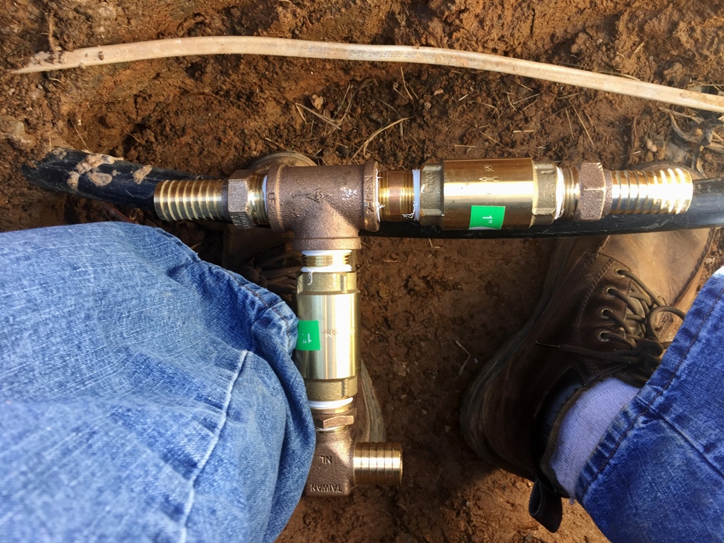
Here is the check valve assembly before installation showing you the length of the ribbed connectors on all ends. You can easily see how far onto those connectors the plastic pipe must be placed and why you must allow for this plus an inch or two extra when measuring where to cut the pipe. Further down the article you will find a photo of the check valve assembly installed with notations. Also shown are my goober white socks and our beautiful red Virginia clay before I started making mud pies.
Warning Two! This one I did not mess up, but I know several people who have. The black plastic water pipe is not very flexible, particularly in cold weather. Trying to push the plastic pipe onto the ribbed end of the connector will be extremely difficult, if not out-right impossible, without first heating the plastic pipe up a bit. The mistake occurs when it is heated too much and deforms/sags/loses its ability to retain/regain its original inside diameter.
Heat it too much and you have a soft mess that, while easy to push onto the connector, will actually now be too lose and not seal properly on the ribbed connector. If you heat it far too much, it will be impossible to push onto the connector because the pipe will retain no rigidity and it will be similar to pushing on a string.
The ribs on the connector are there to bite into the inside of the pipe and hold the pipe in place even under pressure. Heating the pipe too much effectively increases the inside diameter and those ribs never properly bite. I use a propane torch normally used to solder copper pipe and I work slowly and carefully when heating the pipe.
Don’t hold the flame too close to the pipe and constantly move the flame back and forth and around the entire circumference of the pipe. Heat it for several seconds, then pull it off and test the temperature of the pipe with your hand. You are simply trying to warm the pipe, not soften or melt the pipe. Experience has taught me not to let the pipe get so hot I can’t hold it in my hand.
The first connection to make is the one going to the well casing. This one will be easier to handle, therefore the one you should start with as you gain confidence and experience. You will know if the pipe is not warm enough because you will really struggle to push the pipe all the way onto the connector. Back off and continue to apply heat slowly until you can push the pipe all the way up the connector with some effort required. If it slips on easily you have heated it too much.
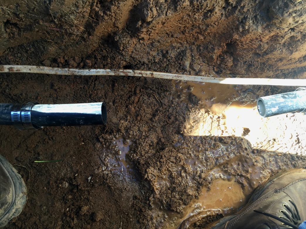
I included this photo to show several things. Note how clean the cut pipe ends are. This is why you should invest $20+ into a plastic pipe cutter big enough to cut the pipe you're working on. Also note the pipe clamps already slipped onto the pipe before I began heating the pipe and installing the check valve assembly. Not shown is the fact I cut it a half inch too short, thought the end results were fine. Finally, you can clearly see the mud pie making has commenced. Bon appetit!
Once you have the first connection finished, repeat the process on the other side of the check valve assembly. Make sure the pipe is the proper length before you heat it and push it on. This is where you will need to bend the plastic pipe while moving the check valve assembly around a bit in order to line up the pipe and push it on. You don’t want to heat the entire exposed plastic pipe, just the end that will slide onto the connector plus another inch or so.
Make sure you tighten the pipe clamps immediately after you make the connection. I never try to use a flat screwdriver when tightening the clamps because the screwdriver slides off easily and the clamps are never fully tightened. Use a socket and driver to tighten the clamps, which assures the clamps are properly tightened.
After you have inserted the check valve assembly into the main line, you still must connect the plastic pipe coming from the modified Pitless adapter to the assembly. Don’t cut the pipe too short and make sure any bends in the pipe are gradual and not abrupt. I made sure I left some slack in the line in case I needed to shorten the pipe later for whatever reason. You have more leeway here because you have plenty of plastic pipe to work with and more room to maneuver the pipe.
Don’t forget to slide two pipe clamps onto the plastic water pipe before heating it and making the connection. Then slide the pipe clamps up into position and tighten them thoroughly. It is best to do this immediately after each connection is made when the plastic pipe is still a bit warm. You want those clamps to bite hard and force that plastic on the inner wall of the plastic pipe to mate well with the ribs.
After the connections are all made and the plastic pipe is back to ambient temperature, check the hose clamps one more time. You don’t want to over tighten, but neither do you want them to be anything other than tight. They are an integral part of the mechanical connection and must be secured properly.
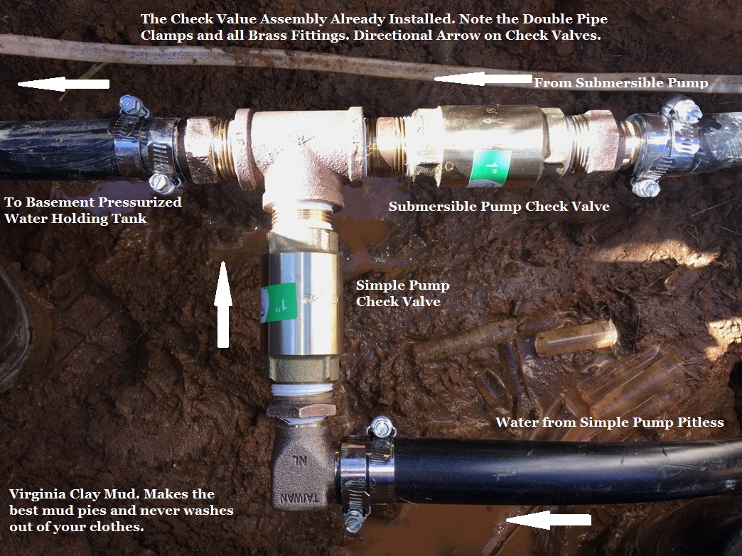
The arrows indicate the direction of the water flow. The two check valves prevent that flow from reversing, so the submersible pump can't pump down the Simple Pump line and vice versa. The well casing is off frame to the right and the house is to the left. The electrical cable at the top feeds power to the pump. Before back filling I placed support under the check valve assembly to prevent it from sagging when back filled.
Warning Three! This is one I almost made several times, but thankfully caught myself before it was too late. The smart thing to do is to slip two stainless steel adjustable pipe clamps onto the plastic pipe BEFORE you push the pipe onto the connector. While you can apply the clamps after the fact, it is more difficult and can be frustrating if you are working in a confined space and can’t see the clamp well.
Be smart and work slowly; think the entire process through to the end, then each step through to the end before starting any work. Give yourself plenty of time to do the work and don’t cut into the water line until you are positive you have everything you need to button it back up, including the need to abandon your original plan of inserting the check valve assembly and just splice in a repair section to get the water back on for the night.
Assume the worst and plan for the worst. You can always return extra connectors and pipe clamps if you don’t use them. But to discover you can’t go forward nor backwards because of an unexpected problem, and the stores are now closed, is not the situation you want to be in. Start this process in the morning (and not on a Sunday) if possible so you can dash to the store if all hell breaks out.
Mama ain’t gonna be none too happy if you come in muddy from head to toe and declare there will be no water until the next day. Divorce has been the outcome of similar situations. At the very least the dog house will be waiting.
Warning Four! Do NOT cover the water line with dirt until you have thoroughly tested the new connections for leaks. This means going back into the house, opening the values you closed and turning on the submersible pump. Ideally you have your helper do this while you watch over your new connection at the well. Make sure you have called your helper on his/her cell phone and the phone line remains open when s/he turns everything back on. You want to be able to get him/her to quickly shut it all back down if you find yourself with a large leak.
So now you’ve tested the submersible pump and one of the check valves by simply energizing the submersible and looking for leaks, then checking for water at a few faucets. But what about the Simple Pump Pitless adapter and its check value? Did you test that?
Once you are certain there are no leaks and the fresh water system is up and running (mama will be very happy) you must shut it back down again (mama not happy…again). Only this time you must simulate a situation where your main water system is down and you need to use the Simple Pump. This requires bleeding off the water (and thereby the pressure) in the pressurized water tank in the basement.
Every household water system is plumbed slightly different, so it is difficult to explain what to do because your situation may be different from mine. The easiest way to do this is to shut off the power to the submersible pump, then open an outside faucet and let the water run until it slows to a trickle or stops completely. Then close the faucet and return to the basement to check the pressure gauge on the water tank.
What? You have no pressure gauge? You should have one. If you don’t, you should either install one or have one professionally installed.
The pressure gauge should read zero or close to zero. It doesn’t need to be zero in order to continue with the test. Just note what the pressure reading is on a piece of paper and then head back outside to the Simple Pump. Leave the submersible pump power off. In fact, if you turned it back on, turn it off and drain the system again.
What you are trying to accomplish is 1) to see if the Simple Pump will pump water into the house (pumping into pressure) and how long that takes. Plus 2) is the Simple Pump check value and associated connections leaking. And you want this to be a real life situation, thus the reason you have drained down the system. Chances are this will most accurately resemble a real life ‘water down’ situation.
Please note that most residential (submersible pump) fresh water plumbing systems are pressurized to a minimum of 30-35 psi and up to 50-60 psi or more. When the pressure drops to 30-35 psi, the well pump kicks on and water is pumped into the holding tank until the pressure reaches 50-60 psi, then it shuts off.
If you have not stood next to your pressure tank for a period of time while the water runs at length, such as when someone is showering, I suggest you do so in order to become familiar with the sounds your system makes when supplying water for a length of time.
There is a water pressure activated ‘switch’ plumbed into your pressurized tank, often found at the base of the tank where the water from the well enters the tank. This is also where you are most likely to find the shut off ‘isolation’ values you previously open and closed while installing the check valve assembly.
While the water is running, you should be able to hear a ‘click’ as the pressure switch closes, turning on the submersible well pump and filling the holding tank, then switches off when it reaches the proper pressure. Get down close to the pressure gauge so you can watch the pressure rise and fall while the pump is turning on and off.
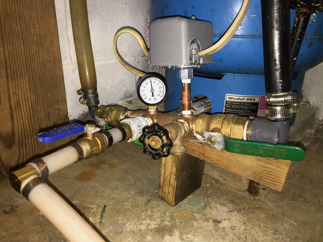
Lots going on in this image. Coming down from the top right is the black plastic pipe feeding water from the well. The green handle on the right is the isolation value cutting off the well from the holding tank/house. The round black knob is a drain valve allowing me to drain the fresh water system at it's lowest point.
The gray box sitting on top of the slender copper pipe in the middle with wires coming out from the left and right is the pressure switch assembly. This cycles on and off the submersible pump when pressure is low or high.
The white faced gauge is the pressure gauge showing at a glance the pressure inside the holding tank. The white plastic pipe coming out to the front left below the gauge with a blue handle on it is the feed and shut off valve sending water to the garden. The yellowish clear pipe coming down from the top left is feeding the house with fresh water. There is a shut off value there which is mostly hidden in this photo.
Off frame to the top left is the large whole house water filter. To the left is the hot water tank. The large blue cylinder in the back is the pressurized water holding tank. I plan on making some upgrades to a few fittings just because some of them look a bit old.
If you are willing to install your Simple Pump, it is imperative you also understand how the rest of your fresh water system works. Chances are if you are in the middle of a regional emergency and without fresh water, there isn’t going to be a plumber handy to quickly respond to your call for help. Know your system and its basic operation.
Trace out all pipe runs and understand where they go and what they feed. Place tags on all valves identifying what each valve does. Be clear and concise with your descriptions. Assume your spouse or a complete stranger is in your house and wants to shut something off. Make notes of major components as well as their model and serial numbers. Inspect anything else you find which appears worn or just plain unusual.
Fix or repair what is broken or leaking. Find an installation or manufacture date on your hot water heater. Personally I would replace a water heater if it is more than 12 years old (less if your water is hard or corrosive) or showing signs of corrosion or leaks. It is not fun to walk into the basement and find it flooded because the water heater decided to pack it in. Be proactive or you will wind up being reactive under less than ideal conditions.
So you are now outside at the Simple Pump ready to test the system. Begin pumping the handle and counting your strokes. You are not concerned so much with time as with the number of strokes needed and the effort required to pump the handle while doing so. I would pump the handle 20-30 times, then stop and walk back inside to check the pressure on the gauge. Don’t be surprised of the pressure has not changed. It eventually will.
The actual Simple Pump ‘pump’ I purchased last year pumps 3 gallons of water per minute. At that time they also had a five gallon per minute ‘pump’, but they suggested I go with the 3 gallon pump because of my static water depth and the fact I was ‘pumping into pressure’. Their newly designed and manufactured ‘pump’ now produces 5 gallons per minute and it appears they no longer produce the 3 gallon pump. This is a good thing.
Regardless, recognize that because you are pumping water into a system that was drained of most of the water and pressure, you must fill the pipes and water tank with a lot of water before the pressure begins to build. This is why you want to pump a certain number of strokes while paying attention to the feel and resistance of the handle, and then check the pressure gauge to note the progress you have made. Made sure you write it all down each time you check so you can refer to it later.
Do not expect to pressurize your water tank to the same upper limit the submersible pump works at. The Simple Pump ‘pump’ is not designed for those higher pressures. Using the hand pump does not mean you can once again take limitless showers and run the water continuously. You will quickly learn how much work it requires to pump enough water into the system to be able to flush the toilet, fill a pot with water for cooking or take a sponge bath.
The situation would be different if you set the system up differently. As explained in an earlier chapter, ideally I would attach a solar panel/battery powered DC motor to the pump head and have that pump run nearly continuously (and slowly) to fill a nearby 1,000-2,000 gallon tank, then hook up a smaller electric pump that would then feed and pressurize the water tank in the basement.
That system will be installed in the future when time and money allows. For now I simply want to be able to deliver fresh water to my home under any conditions and during any emergency by just walking outside and hand cranking the Simple Pump.
Back to the Simple Pump test. After 20–30 cranks on the lever, check the reading on the pressure gauge on the water tank. Resist the urge to turn on a faucet to ‘see’ the water and pressure. Head back to the Simple Pump and crank in another 20-30 pumps of the lever. Check the pressure again. Remember, you are filling the nearly empty pipe headed to the house, the holding tank and some pipes inside the house, so it might take a while before the pressure begins to build. Take plenty of notes.
Once you have the system pressurized to 30-35 pounds (less work than you think, more work than you’d hoped for) head inside (take off those muddy boots or the spouse will clobber you over the head) and flush a toilet, then listen as it refills. Turn on a faucet and watch the flow and pressure of the water. Depending on how much you drained the entire house of water before you started the test there might be air in the lines. As the air escapes the pressure will drop…quickly in some cases.
Essentially you are becoming familiar with your household plumbing system running at a reduced water pressure. You are not trying to duplicate your old fresh water system. Instead you are utilizing the pathways from the old system for water delivery from the Simple Pump. If you expect nothing to change between the submersible pump and the Simple Pump, you will be very disappointed.
Once all the air is out of the system at all the faucets and toilets you would use in an emergency, pump the system back up to 30-35 psi and flush the toilets and use the faucets again to get an idea how much water is available each time you have manually pumped the system up. If at all possible, include the spouse in this part of the experiment after preparing him/her with reduced expectations. Explain that the alternative to the reduced water pressure and flow after hand cranking the Simple Pump outside is to carry in buckets of water from outside and fill toilet tanks and sink basins by hand with the bucket.
Time invested at this point learning about your Simple Pump is an excellent investment and well worth your time. If you can’t do it immediately after installation, conduct these tests later. But do them, again while taking plenty of notes. The key is to manage both yours and your spouses expectations.
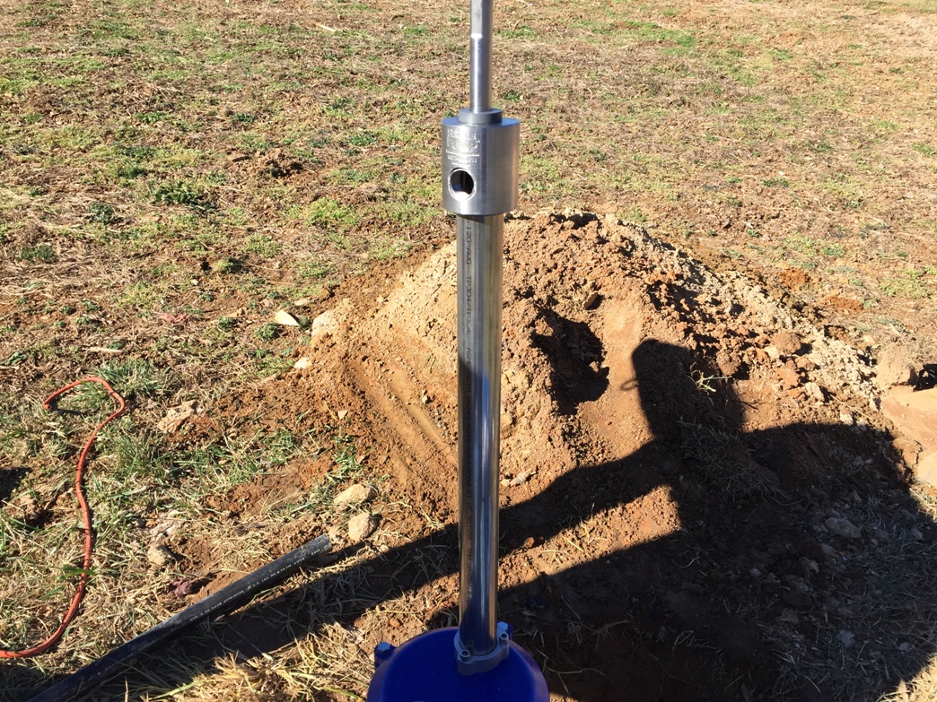
Basically this image is out of order and not in sync with the text. But I wanted to show the Simple Pump head installed on the well casing cap without the lever arm attached to the 24 inch stainless steel rod exiting from the top. Please note the hole in the side of the head near the top. When conducting a 'standard' Simple Pump installation, a brass fitting, check valve and pressure gauge assembly would screw into that hole and water would be pumped out of it. In my case I plugged that hole with a white plastic plug which can be seen in the final photo at the bottom of this article.
Finally I wish to address a unique situation with the well casing and cap used in my system. The Simple Pump web site breaks out component pricing, allowing the reader to examine individual components and sizes. Of particular note is the large assortment of well casing caps, a testament to the various casings used throughout the country/world. While there might be a ‘standard’ sized well casing/cap used in your area/region, there is no ‘standard’ size used country wide.
Pay particular attention to both the inside and outside diameter of your well casing. In my case the outside diameter (OD) was 6 ¾ or 6.75”. Therefore the best, but not perfect, choice was the C7WTCC-CI cap designed for Pitless adapter installations with a casing OD of 6.9” to 7.0”. As you can see, the cap was slightly larger than needed. But because it had a range of OD’s I thought there would be enough ‘play’ in the cap’s compressible gasket to make up for the smaller sized casing. Unfortunately this did not work out as planned.
I’m uncertain if the next size smaller would have worked as well. It’s designed for a 6.625” well casing, an eighth of an inch smaller than my casing. While it might have fit, it might not as well. I decided to stick with the cap I had and if I wasn’t able to jury rig a fix, I would order the smaller cap from Simple Pump and try to make that one work. This is the advantage of using the Pitless adapter. You can open the well and switch caps relatively easily because you aren’t dealing with the weight of the entire drop pipe/sucker rod stack.
After installing the pump head and lever, then tightening the cap and finding it wasn’t tight enough, I did some initial testing and then let everything set while I thought about various methods I could use to fill the gap by making the OD of the casing ‘larger’. I needed something to fill the gap evenly and smoothly, that could be applied in layers if I underestimated how much I needed and wouldn’t corrode or rust in the weather. It was a tall order and I was stumped for a few days until I realized I had the material on hand to solve the problem.
And the solution was a roll of aluminum flashing left over from a previous project. I grabbed the roll and measured the thickness of a dozen layers, then extrapolated that finding into how many layers I would need to wrap around my well casing. I took that number and multiplied it by the actual length around the outside of the casing to find the length of flashing I needed to cut.
The one potential impediment I could foresee when installing this ‘padding’ was the smaller section of pipe attached to the casing cap that routes the power cable down into the ground. This smaller diameter pipe is used to protect the wire from damage from string trimmers, lawn mowers and so on. The pipe is less than an inch from the main well casing, so working with a long piece of flashing could be problematic.
I wound up loosely wrapping the flashing around the casing, then using strong duct tape to anchor the ‘inside’ end of the flashing to the well casing while making sure the top of the flashing was even with the top of the well casing. Then I clamped a vice grip onto the outside end of the flashing and slowly pulled the flashing tight around the casing, making sure I pushed it up to the top as I tightened.
Remember, the well casing cap was still in place, so I needed to work the flashing up under the cap while I tightened it. The alternative was to disassemble the head and lever so I could pull the cap completely and install the flashing. I did manage to slip one end of the cap up enough to take the picture you see here.
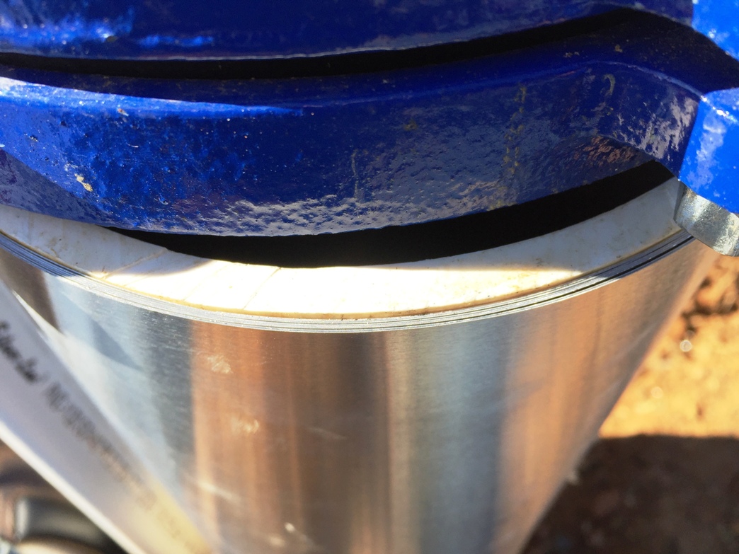
Here you can see the aluminum 'padding' I added to the outside wall of the well casing so the well cap would fit tighter. After viewing this picture up close I'm wondering if the next size smaller cap might just work after all. Like I said in the piece, after running a full series of tests I will determine if this fix is suitable or if I need to go with the smaller size. I will update this article if I do so.
Once the flashing was installed I then tightened the bolts on the cap and immediately noticed the difference. While previously the cap only began to feel snug when I reached the end of the range of the adjusting bolts, but never fully tightened, now it immediately began to snug up and was completely secure long before I reached the end of the adjusting bolts. This was an elegant solution to a difficult problem.
I am still prepared to purchase the smaller well casing cap if my ‘fix’ fails under sustained usage. I will get a better feel for if the repair is sustainable after I conduct several tests of the system. We have now had several weeks of bitter cold, high winds and snow so I’ve put off final testing until the weather is not a complicating issue and I can concentrate on measuring performance and physical effort.
While using a modified Pitless adapter with my Simple Pump has somewhat complicated the installation, it has simplified the actual use of the pump, particularly during the winter. When I expand the system to include the solar powered motor and external storage tank I can still use the Pitless adapter and check value assembly by slightly modifying it.
Rather than have the water flow from the Pitless adapter directly into the check valve assembly, then into the house, I can simply route the water from the Pitless adapter directly to the storage tank underground via a dug trench, then have the storage tank feed pressurized water (using an off the shelf small DC pump) using the same trench back into the check value assembly and on to the house.
By installing the modified Pitless adapter now, I don’t need to mess with the Simple Pump drop/discharge pipe installation later when I expand the system. A relatively small additional investment in time, money and material now will pay off tremendously later when I expand. And even if I never expand beyond the present setup I have protected myself from freezing and external contamination to the best of my ability. In my view this benefit alone is well worth the added effort and expense.
If you are a novice to this type on work, or even somewhat accomplished when it comes to simple repairs around the house, the Simple Pump is a project you can certainly tackle if you properly plan and thoroughly prepare before you start the installation. The rule of thumb with any project you might consider to be over your head is to plan, prepare and ask lots of questions, including the most important question of all.
“What question(s) don’t I know to ask?”
01-27-2016
Cognitive Dissonance
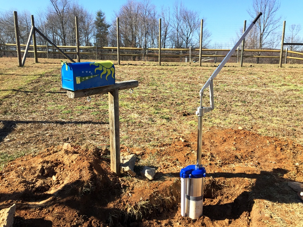
The completed Simple Pump installation. The final grading will need to wait for the spring thaw. It may not look like it, but that ground is rock solid. The custom painted mailbox to the left holds Mrs. Cog's garden hand tools when the garden is in session. The 8 foot fence in the background was designed to keep the deer from jumping over, the large black bears from pushing through and the bunnies from digging under. So far so good.