The Simple Pump
Part Two
By
Cognitive Dissonance
The following is the second of three articles outlining the research, preparation and installation of the Simple Pump, a high quality mechanical pump used both in everyday applications such as a ranch, farm, off grid cabin or homestead as well as an efficient backup to an existing fresh water pumping system. These are long reads, not brief outlines, and apply only to our specific situation and location. Your experience can and will vary from ours.
When last I left you it was December of 2014 and I had prepared my existing well for the Simple Pump installation by pulling up all 300 feet of submersible pump and pipe, clearing any obstructions down to 160 feet, installing a Pitless adapter in the well casing to freeze-proof my regular fresh water supply and cut 25 feet off the bottom of the submersible discharge pipe to get the pump up and out of the silt at the bottom of the well.
I failed to mention in the last chapter one last step I preformed before I buttoned everything up in time for the hard-on-my-heels winter. Anytime you open up your well you risk introducing contaminants to the water. This is why you cannot leave it uncapped overnight, let alone open and unsupervised during the day.
If I had just opened the well to measure the static water level, then closed it back up, all I might do is test the water several days later for issues such as E coli bacteria. But if I pull the submersible pipe and pump up the well and haul it out on my lawn, which the birds and animals just happen to use as their toilet, I assume the pipe has been dragged through contamination and my fresh water supply is no longer fit to drink.
It is then that I ‘shock the well’ aka disinfect the well, which entails pouring chlorine bleach down the well casing, then running the water for a long time to clear out the chlorine. This effectively disinfects the entire fresh water system from well to pressure tank to tap and everywhere in between.
There is actually much more involved than just running the water afterwards to properly disinfect your system. I have included a link to some instructions. Please read them carefully and then consult several other sources to confirm you understand what you are doing.
Fast forward almost exactly one year to December of 2015. Life slowed down a bit and I decided the warm early winter weather was my last best chance of getting the Simple Pump installed before I began my next project……the construction of a new barn right in the teeth of another cold winter.
I never learn, do I?
When I purchased the Simple Pump last year I knew I wanted to integrate it into my existing fresh water system. Or as the Simple Pump website explains, I wanted to “pump into pressure”, meaning hand pump the water up the well and directly into my home’s pressurized water tank where it would then be delivered to every faucet, toilet and shower using my existing fresh water distribution system. No carrying buckets of water for me.
However, I had not decided if I was going to use a Simple Pump modified Pitless adapter and route the water through the side of the well casing and into the main underground water line headed to the house. By 'modified' I mean slightly different from a ‘standard’ Pitless adapter, one altered to work with the Simple Pump. The alternative would be to execute a straight forward Simple Pump installation with the water exiting the Simple Pump head. From there it would be routed into my home water system via a potable water hose attached to an outside faucet.
My solution was to purchase components for the two different applications, adding a few hundred dollars to the bill, but affording myself maximum flexibility.
After several emails back and forth with the Simple Pump representative I was presented with a semi-detailed invoice (more on this later) and instructed to call the home office so I could pay using my credit card. My call was promptly answered and the charge complete. I was quite pleased when I was told my order would arrive before Christmas. Who doesn’t want Santa to bring them their very own Simple Pump, though I wasn’t exactly sure how he would fit it down the chimney.
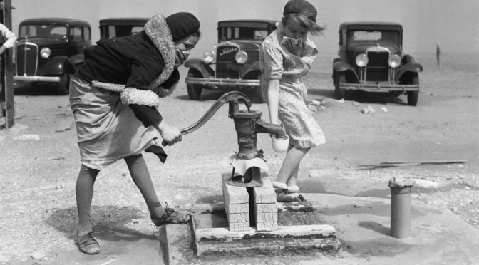
As it turned out FedEx was assigned the task of administering the pre Christmas delivery. The Simple Pump’s discharge/drop pipe comes in 9 foot sections and I had ordered a total of 15. Add that to the remaining components and the package turned out to be a shipping tube about 12 inches in diameter and a little more than 9 feet long. And quite heavy to boot.
Unfortunately, when Santa arrived he had bad news. The shipping tube was damaged and broken open in the middle. I emailed Simple Pump at the email address on the bottom of the invoice and quickly received a reply directly from the CEO. Customer service doesn’t get any better than that and precisely why I want to do business with a quality small company.
Santa Claus, aka FedEX, hates me.
I was uncertain exactly what was missing since the invoice was not completely itemized; instead both individual parts and component groups were listed. I laid out all the parts and snapped several images, then attached them to the email conversation. I was told I was missing only a small PVC plug and it would arrive via Priority Mail in a few days. Christmas was saved.
Then life got busy……and remained so for nearly a year.
Fast forward a year to December of 2015. While I had reviewed the installation documents after I received the Simple Pump, since a year had passed I pulled them out and went over them again. There are also excellent installation videos on the Simple Pump website and I strongly urge anyone considering installing the pump to watch them.
While the installation is quite simple, there is nothing comparable to watching what you just read. However, do not rely solely on the video for directions. Read the installation documents carefully.
A key component of the Simple Pump package is a new well cap sized to fit your particular well casing. It is imperative the cap sits level and evenly on your well casing, since the new cap supports the Simple Pump head and pumping arm. Because of this, the cap must be able to contain the torque and pressure applied to the pump head when you are moving the pump handle up and down.
In my situation, the well casing had been rough cut by the driller and never cleaned up. Since the original casing cap was actually a plug, therefore seated inside the casing and not on top of it, it wasn’t important for the casing to be level and clean cut. It is important now.
So how does one make a clean perpendicular cut to a length of pipe when the pipe is placed vertically in the ground and barely 12-16 inches above the surface? The actual cutting isn’t that difficult. A circular saw set for a medium depth cut while fully seated on the pipe, along with plenty of patience, will suffice. That and a flexible back/body, plus the ability to use the circular saw while lying on your side, helps immensely.
Or you might find a friend or rental tool company with a very large pipe cutter. But using a pipe cutter requires cutting a few inches off the end of the pipe and I did not have any excess pipe to cut. It was already less than 18 inches above the surface, the ideal length above ground.
Marking the pipe for the cut is an entirely different matter and loaded with potential problems for the uninitiated. The way I mark a (large) pipe or other round tube (without a square edge) for cutting is simple. Grab several sheets of printer paper and tape the pieces together until you have a length of paper long enough to go completely around the pipe with several inches of overlap.
In effect what I am creating is a long piece of paper with a straight edge. In order to keep my paper edge straight I overlap each piece of paper onto the next at the half way mark and thoroughly tape them together, then add the next piece. Make sure the papers are perfectly aligned with each other. This helps to prevent errors from compounding.
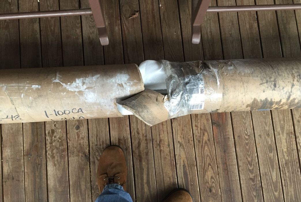
The finished length of paper (in my case I needed at least 24 inches), when placed on its long edge, should be flat with no gaps. I used the kitchen table as a reasonably flat surface to make sure my paper had a true ‘straight edge’. I then grabbed my scotch tape and black magic marker and headed to the well casing where I wrapped the paper around the casing, making sure it matches perfectly top and bottom where the paper overlaps. Take your time and do this right.
Well casing wrapped in paper in order to mark a perpendicular edge to cut.
After taping the paper in place I used a black ‘sharpie’ to mark the edge. Presto! A reasonably clean straight edge is created at a right angle to the length of pipe. All that remains involves careful cutting and a rasp or file to clean up any imperfections.
Be sure you plug the casing pipe near the top with a towel or cloth, making sure it fits tightly inside the well casing below where you are cutting so both the towel and pipe cuttings don’t fall down the well. There are other methods you may use to make a straight pipe cut. I suggested this one simply because nearly everyone has some printer paper and tape hanging around.
Whatever you do, please refrain from cutting the power cable exiting from the top of the well casing. Get someone to help you hold, and move, it out of the way as you cut. Or stop several times while cutting to relocate the cable out of harm’s way. There is usually some slack in the power cable to allow you to maneuver it away from the blade.
Make sure you test fit the new well casing cap before proceeding to the next step. If it rocks on top of the casing, even just a little, determine where the high spot is and knock it down with the rasp or file. You want the cap to be rock solid on the well casing in order to dissipate the torque applied to it while using the Simple Pump. Take your time and do this right the first time.
Did I forget to tell you to kill the power to the well while working on it? Never ever assume the power is off, even after you (think you) have killed the power via circuit breaker, fuse or switch. There might be a dozen reasons why there is still power to the well, including something as silly as you hitting the wrong circuit breaker or the spouse noticing the water is down and resetting the circuit breaker without realizing you deliberately shut it off.
After shutting off a circuit breaker I always cover the breaker switch with a piece of black electrical tape to let others know the breaker is off for a reason and didn’t just trip. I then grab my volt meter and test for power where I’m working, in this case the well casing. There should always be a power cable splice at the top of the well casing between the line coming from the house and the line running down the well.
This is where you will disconnect the splice and test the line coming from the house with your volt meter to make sure the power is really off. You could also turn on a tap and see if the pressure remains steady, which means you did not turn off the pump, or if the pressure gradually drops down to nothing, which means you probably did.
I don’t like doing this for several reasons. It is an indirect indication of no power that could be caused by many other things. It is entirely possible for another component to fail at this moment, giving you a false indication of no water pressure, therefore no power, particularly if you have been messing with pipes, wires and connections. And now I have no pressurized water remaining in the house other than the standing water in the toilet tanks.
The best way to test for no power is with a meter you know to be working. I try to remember to check the meter at an outlet that is working before using it to measure alternating current (AC). More than once I have found the meter inoperative because of dead batteries or a blown internal fuse.
If you don’t have a meter I suppose you could carefully swipe one of the ‘hot’ wires to the ground wire. If the power is still on, the large flash and sparks will be the clue you are looking for. I do not advocate doing this since you can easily grab a live wire and light up your life. Save yourself the shocking risk and buy yourself an inexpressive volt/ohm meter. There are dozens available on Amazon or elsewhere for less than $20. Personally I would spend more money and purchase a higher quality meter.
Whatever you do, don’t drop the power cable down the well when you disconnect it from the cable coming from the house. If you lose it down the well you will be pulling the pipe and submersible pump up at least far enough to retrieve the cable.
You might get lucky and find the power cable taped to the submersible drop pipe near the surface, allowing you can grab it with a pole and hook. My method is to securely tie a safety rope to the power cable going down the well, then tie that rope to something heavy nearby before I break the electrical/physical connection. An ounce of prevention here is worth a pound of cure. Murphy and his damn law are always lurking.
With the well casing cut and the new well cap test fitted, it's now time to start digging into the Virginia clay and gravel, my favorite of all homestead activities. The Pitless adapter for the submersible pump is buried about 16 inches below the surface and 30 inches from the top of the casing as described in Part One.
However, the modified Simple Pump Pitless adapter must be placed at least 48 inches down from the top of the well casing to facilitate the proper alignment of the ‘sucker’ rod connection to the Simple Pump head on top of the well casing. This meant I would need to dig down about four feet from the surface to give me room to maneuver and install the Simple Pump Pitless adapter.
A man who owns a backhoe would just chew away at the dirt until the excavation was deep and wide enough for a person to comfortably work down there. A man with a shovel and a bad back digs just enough to shoehorn his body (head first) down the hole to do the work.
Picture for yourself a large man (tall and…err…modestly wide) pushing 60 years old, diving head first into the rat hole to drill out the casing and install the Pitless adapter, then attach the one inch water pipe. Complicating the procedure is the blood is rushing to his head, his left shoulder jammed against the pipe casing and his right shoulder to the side of the hole, limiting his ability to use his arms and hands but helping to prevent him from falling all the way to the bottom head first.
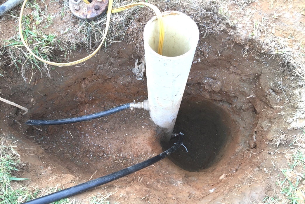
The Rat Hole. The pipe on the left, which runs to the house, is connected to the submersible pump Pitless adapter. The pipe on the right is the just installed modified Simple Pump Pitless adapter. That pipe is not yet connected via two check values to the pipe on the left.
Now picture his petite wife, not even half his weight, sitting on his butt and/or feet to keep him tenuously anchored to the surface of Mother Earth lest he be prematurely buried six feet under (four actually) then pulling for dear life on his belt and/or feet as the man attempts to push himself back up the narrow hole. Now repeat this maneuver at least twelve times in order to complete the task at hand.
It was worse than that.
In fact it was so bad at one point I was laughing out loud at the absurdity of the situation, despite the growing deep bruise on my left shoulder and nearly half my blood supply permanently relocated to my head. I simply cannot describe how difficult it is working upside down in a dark hole for any longer than 30 to 40 seconds at a time. To complicate matters just a bit more, my chest was compressed against the side of the hole making it very difficult to breathe.
Next time I find/pay a friend with a backhoe or make sure there is no next time.
While digging my hole to China I also dug out the water line/Pitless adapter for the main submersible pump since I was going to connect the two systems together to integrate the Simple Pump into my fresh water system. Did I mention Virginia clay mixed with Virginia gravel is essentially what the Egyptians used to make the pyramids?
Each time I put spade to earth around here my respect for the early settlers of Virginia increases exponentially. Most of the open fields in the surrounding area were cleared by hand and animal more than a century ago. They were better men and women than I.
With the modified Simple Pump Pitless adapter installed I turned to the pump and discharge/drop pipe installation. I did not install the check value assembly between the Simple Pump output pipe and the main water line to the house at this time because I wanted to make sure the Simple Pump was pumping water before integrating it into the house's water system and burying the connection. Rule number one when working with underground pipes is to make sure the installation or repair actually functions before dumping the dirt back in.
While I strongly suggest you visit the Simple Pump website for a more detailed explanation of how the pump actually works, its operation is simplicity itself. Basic ‘suction’ pumps won’t function much beyond 20-25 feet because of the limits of atmospheric pressure. One of the problems explaining a pump to laypeople is the terminology has been distorted over time.
With basic ‘suction’ hand pumps, you aren’t actually ‘sucking’ water up the pipe. Instead you are removing (some of the) air from the pipe and the 14.7 pounds per square inch (PSI) of atmospheric pressure at sea level is pushing down on the well water and therefore water up the pipe to fill the space where the air was just removed. There is a limit to what 14.7 PSI can do when dealing with gravity.
Therefore, anything deeper than a very shallow well requires another solution. That solution usually results in placing a pump at the bottom to push water up to the surface. This pump can either be mechanically, hydraulically or (in the case of the vast majority of home well systems) electrically driven. This is the simple explanation; there are exotic alternatives if you have lots of money and quality engineering.
So how does one transfer the mechanical energy derived from moving a handle at the surface down to the pump in the well? Well, (pun intended) with a ‘sucker’ rod of course.
The Simple Pump water discharge/drop pipe runs all the way down to the pump at the bottom. Obviously the primary purpose of this pipe is to funnel water from the pump to the surface. But this discharge/drop pipe has room to spare inside to also contain a fiberglass ‘sucker’ rod. This rod is connected to the pump at the bottom and the handle at the top. Essentially when you move the handle at the top you ‘energize’ the pump at the bottom via the ‘sucker’ rod inside the discharge/drop pipe.
If I understand this correctly, moving the handle to the down position pulls the rod up, which by virtue of being connected to the pump at the bottom draws water into the pump. Pulling the handle up pushes the rod down which in turn ‘pumps’ the water already in the pump up the pipe a distance. Do this enough times and the water reaches the surface. The discharge/drop pipe acts as a conduit for both the water and the rod that conveys the mechanical force to the pump.
Amazingly simple.
As you might imagine, the pump at the bottom of that long pipe must be of very high quality in order to efficiently convert a vertical mechanical force into a pumping action that not only will force the water up one hundred feet, but then into a pressurized tank. It takes 0.434 PSI to raise water one foot. If my static water level is 100 feet down, the pump must exert 43.4 PSI of pressure to get the water to the surface.
If that water is then pumped into a pressurized tank at 35 PSI (pumping into pressure) the precision pump at the bottom must be able to create at least 78.4 PSI (43.4 + 35) to meet my needs. To add to the challenge, the pump handle must be easy to operate so my petite wife and daughter can move it without too much effort.
No matter how you look at it, this is a tall order to fill. And based upon my research, for the price, no other hand operated pump on the market can do this. In fact, based upon their website claims, the Simple Pump can pump from even greater depths into pressure.
Simply amazing.
Each 9 foot discharge/drop pipe section is shipped with a 9 foot fiberglass ‘sucker’ rod inside. As discussed earlier, one year elapsed between the time I received my shipment and when I began installation. While everything was safely stored during that time, the installation instructions strongly suggest the discharge pipe and rod be washed inside and out with a weak bleach solution to, in effect, ‘disinfect’ the pipe and contents before it is lowered into your fresh water supply.
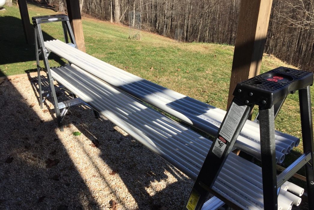
After washing in a weak bleach solution, the pipes and sucker rods (hidden inside the pipe) are left out to air dry.
I set up two step ladders to act as a storage rack, then mixed up the bleach solution and carefully washed the pipes and rods before laying them out to air dry. The Simple Pump instructions give you the bleach to water proportions. I then reopened the well (a day had passed since I cut the well casing) and placed the new well cap on the casing. Quickly I began installing the pump and discharge pipes, taking great care to make sure all connections were secured as outlined in the instructions. Don’t forget the pipe tape on the pipe threads. Three turns only, no more, no less.
I urge you not only to read the Simple Pump website instructions, but to watch the installation videos as well. It is very easy to accidentally drop all those pipe sections down the well if you’re not careful to use the included ‘safety tool’ while installing the drop pipe. I would also suggest you don’t do this alone, but instead grab a friend and review the instructions with them before beginning.
The installation is simple, but there are several points where you will be handling substantial weight and an extra set of hands is certainly required. I think each section of discharge/drop pipe weighs about 5 lbs. I was handling 15 sections, which means I was dealing with around 75 pounds, plus the weight of the pump and any water in the pipe.
Boyz and their toyz stupidity alert! Like a kid in a candy store, once I had all 15 pipe sections installed I couldn’t resist trying out the pump. While the head and lever were not installed, I could grab the short section of ‘sucker’ rod sticking above the last pipe section and move it up and down by hand. While the pump was nearly 135 feet below the surface, and more than 35 feet below the static water level, it only took 65 strokes of the ‘sucker’ rod to move water all the way to the surface. Yeah!
My joy at seeing water cascading from the pipe quickly turned to dread when I suddenly realized I’m a dumb ass. What I had just done was filled the pipe with fresh water, water which weighs more than 8 pounds per gallon. Since the tough part of the job remained, that of physically holding the pipe while I attach the remaining pieces, then mate it to the modified Pitless adapter, this fool just made his job that much tougher.
Calmly I grabbed the top pipe section, which was supported by the safety tool still in place, and slowly lifted it to test the weight. Sure enough it was heavier than when I had installed the last pipe section. Thankfully it wasn’t that much heavier and I was certain my buddy and I could handle the weigh when we moved on to the next step. It did enlighten me to what I would deal with weight wise if I ever needed to pull the Simple Pump back up for repairs.
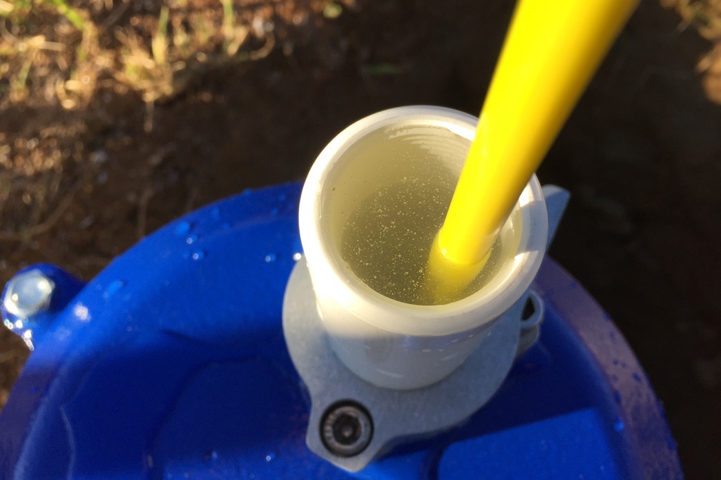
Evidence of Stupidity.
Approximately two seconds after the water appeared at the surface I realized my mistake. Hopefully you don't make the same error.
I point out my stupidity so you don’t follow in my footsteps. A better time to test the system would have been after it was mated to the Pitless adapter and I no longer had to physically hold the entire weight of the drop pipe/sucker rod system. Like I said…boyz and their toyz. Clearly the section of my brain controlling impulsive behavior, thereby short circuiting logic and reason, still hasn’t fully developed.
I had only planned to install the discharge/drop pipe sections that day because I started late and didn’t want to work in the dark. This was exactly why I ‘tested’ the system. I just couldn’t wait until the next day. After securing up the well I reviewed the separate instructions for installing the special hardware needed to route the sucker rod through the modified Pitless adapter and on up to the head and handle.
Remember, the water exits the Pitless adapter through the side of the well casing and on to the house. But the ‘sucker’ rod inside the pipe, which is first connected to a smooth stainless steel extension, must go up through the (modified) Pitless adapter to be connected to the handle at the top. This is where I ran into problem number two, another missing component (a ‘rod gland’ to be precise) which clearly ‘exited the shipping tube’ a year ago and was overlooked both by myself and the Simple Pump CEO.
Can you say ‘full stop’?
I immediately found the email thread of my conversation with the CEO about the damaged shipping container from a year ago and forwarded that along with my latest plea for help. Personally I would not have been surprised if he had told me tough luck since it had been one full year.
In my defense the shipping invoice did not contain a complete itemized list, but rather some itemized components and several ‘assemblies’ which were groupings of non itemized parts. This was why I snapped pictures of all the parts when I originally emailed the CEO about the damage. There was just no way I could figure out what was missing without an itemized list.
Despite it being the height of the holiday season, I was incredibly pleased the CEO promptly answered my email with good news, bad news. He was happy to ship me the missing part free of charge, but it was presently out of stock and it would be at least a week until the rod gland shipped. As promised the missing part arrived within 10 days and I was back in business.
I will leave it here and finish up the Simple Pump installation with the third and final chapter of this series. Stick with me, we’re almost there.
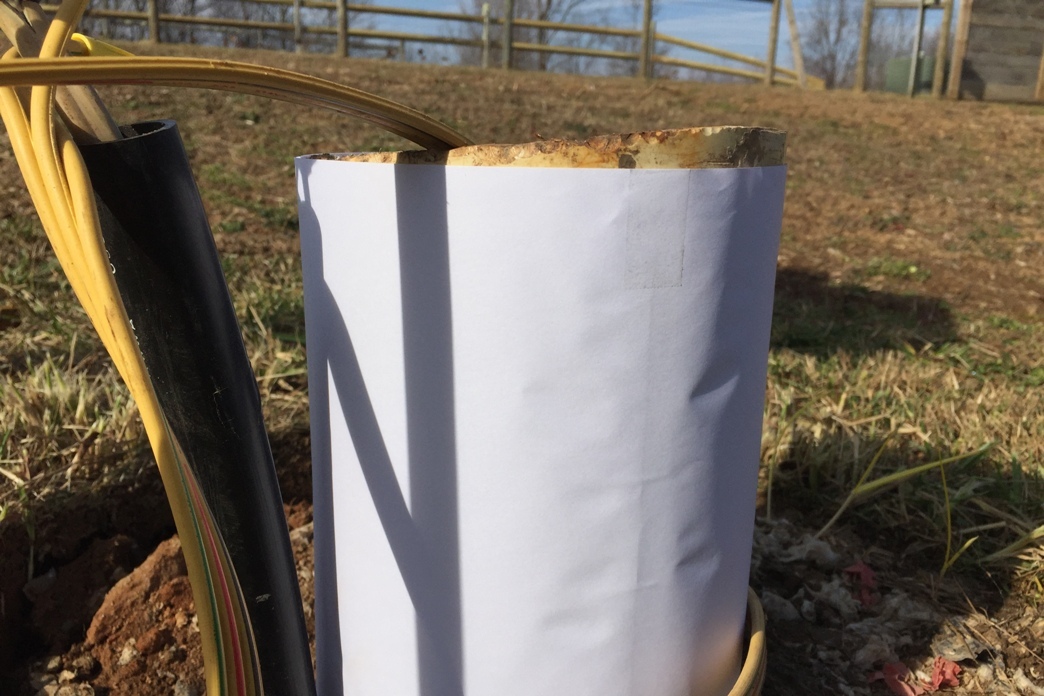
01/05/2015
Cognitive Dissonance
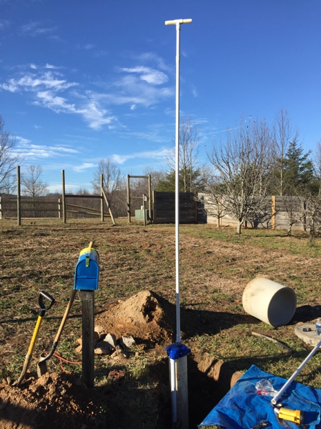
An image of the new well cap (temporarily) in place with a section of 'sucker' rod (hidden inside) and discharge/drop pipe in place and ready to be lowered. The 'T' at the top is a safety handle used to help cope with the weight of the installed pipe.